Design
How to check electronic components with Multimeter
Nov
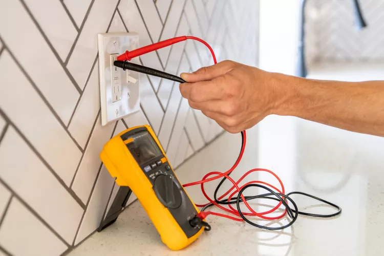
We can test resistors, capacitors, inductors, diodes, LED, transistors, and continuity of a circuit with the help of a multimeter.
Are you eager to learn how to test electronic components like a pro? Look no further than ‘The Ultimate Guide to Testing Electronic Components: A Step-by-Step Tutorial’. In this comprehensive article, we will walk you through the essential techniques and tools you need to accurately test electronic components.
Whether you are a beginner or an experienced technician, this step-by-step tutorial will equip you with the knowledge you need to confidently diagnose and troubleshoot electronic devices. Discover the secrets to identifying faulty components, using multimeters and oscillators, and interpreting test results.
With our easy-to-follow instructions and real-world examples, you will master the art of component testing in no time. No longer will you be left scratching your head when faced with a malfunctioning circuit or device.
So, if you’re ready to take your electronics troubleshooting skills to the next level, dive into ‘The Ultimate Guide to Testing Electronic Components: A Step-by-Step Tutorial’ and become a confident and efficient problem solver.
Importance of testing electronic components

Testing electronic components is an essential part of troubleshooting electronic devices. It allows you to identify faulty components and replace them, which can save you time and money in the long run. By testing components, you can also determine whether a device is repairable or needs to be replaced.
Testing components is also important for ensuring the safety of electronic devices. Faulty components can cause devices to malfunction or even cause electrical shocks, which can be dangerous. By testing components, you can ensure that devices are functioning properly and are safe to use.
Common tools and equipment for testing electronic components
Before we dive into the step-by-step guide for testing electronic components, let’s take a look at the common tools and equipment you’ll need.
Multimeter: A multimeter is a versatile tool that can measure voltage, current, and resistance. It is essential for testing electronic components.
Oscilloscope: An oscilloscope is a tool that allows you to visualize and measure electrical signals. It is useful for testing electronic components that produce waveforms, such as capacitors and diodes.
Signal generator: A signal generator is a tool that can produce various electrical signals, such as sine waves and square waves. It is useful for testing components that require a specific input signal, such as transistors and ICs.
Soldering iron: A soldering iron is a tool used to solder components onto a circuit board. It is useful for replacing faulty components.
Desoldering pump: A desoldering pump is a tool used to remove solder from components and circuit boards. It is useful for removing faulty components.
Step-by-step guide to testing resistors

Resistors are electronic components that resist the flow of electrical current. They are commonly used to control the amount of current flowing through a circuit. Testing resistors is a simple process that can be done with a multimeter.
1. Set your multimeter to the resistance (ohms) mode.
2. Identify the resistor you want to test.
3. Place the multimeter probes on either side of the resistor. Make sure the probes are making good contact with the resistor leads.
4. Read the resistance value on the multimeter display. Compare the value to the marked resistance value on the resistor. If the values match, the resistor is working correctly. If the values do not match, the resistor is faulty and needs to be replaced.
Step-by-step guide to testing capacitors
Capacitors are electronic components that store electrical charge. They are commonly used to filter and regulate electrical signals. Testing capacitors requires a bit more equipment than testing resistors.
1. Set your oscilloscope to the AC voltage mode.
2. Identify the capacitor you want to test.
3. Connect the oscilloscope probe to one of the capacitor leads.
4. Connect the signal generator to the other capacitor lead. Set the signal generator to produce a sine wave with a frequency of around 1 kHz and an amplitude of around 5 volts.
5. Check the oscilloscope display. You should see a sine wave that gradually charges and discharges. If the waveform is distorted or does not charge and discharge, the capacitor is faulty and needs to be replaced.
Step-by-step guide to testing diodes

Diodes are electronic components that allow current to flow in only one direction. They are commonly used to rectify AC signals into DC signals. Testing diodes requires a multimeter.
1. Set your multimeter to the diode mode.
2. Identify the diode you want to test.
3. Place the multimeter probes on either side of the diode. Make sure the probes are making good contact with the diode leads.
4. Read the voltage value on the multimeter display. If the voltage value is around 0.7 volts, the diode is working correctly. If the voltage value is outside of this range, the diode is faulty and needs to be replaced.
Step-by-step guide to testing transistors
Transistors are electronic components that amplify and switch electrical signals. They are commonly used in amplifiers, oscillators, and digital circuits. Testing transistors requires a multimeter and a signal generator.
1. Set your multimeter to the diode mode.
2. Identify the transistor you want to test.
3. Place the multimeter probes on the base and emitter leads of the transistor. Make sure the probes are making good contact with the leads.
4. Read the voltage value on the multimeter display. If the voltage value is around 0.7 volts, the transistor is working correctly.
5. Place the signal generator probe on the base lead of the transistor. Set the signal generator to produce a sine wave with a frequency of around 1 kHz and an amplitude of around 5 volts.
6. Check the oscilloscope display. You should see a waveform that is amplified and inverted. If the waveform is distorted or does not amplify, the transistor is faulty and needs to be replaced.
Step-by-step guide to testing integrated circuits (ICs)

Integrated circuits (ICs) are complex electronic components that contain many interconnected transistors and other components. They are commonly used in digital circuits and microcontrollers. Testing ICs requires a multimeter and a signal generator.
1. Identify the IC you want to test.
2. Consult the IC datasheet to determine the pinout and function of each pin.
3. Connect the signal generator probe to the input pin of the IC. Set the signal generator to produce a digital signal with a frequency of around 1 kHz and an amplitude of around 5 volts.
4. Connect the oscilloscope probe to the output pin of the IC.
5. Check the oscilloscope display. You should see a waveform that matches the input signal. If the waveform is distorted or does not match the input signal, the IC is faulty and needs to be replaced.
Troubleshooting tips for testing electronic components
Testing electronic components can be a time-consuming process, especially when dealing with complex circuits and devices. Here are some troubleshooting tips to help you diagnose problems faster and more efficiently:
1. Start with the basics: Always check the power supply and connections before testing individual components. A loose connection or a bad power supply can cause a device to malfunction.
2. Use the right tools: Make sure you have the right tools and equipment for the job. A multimeter and oscilloscope are essential for testing electronic components, but you may also need signal generators, soldering irons, and desoldering pumps.
3. Consult datasheets: Always consult datasheets for electronic components and devices. Datasheets provide valuable information about component pinouts, functions, and specifications.
4. Be patient: Testing electronic components can be a time-consuming process. Take your time and be patient. Rushing through tests can lead to inaccurate results and wasted time.
5. Double-check your results: Always double-check your test results before replacing a component. A faulty test result can lead to unnecessary component replacement and wasted time.
Conclusion

Testing electronic components is an essential part of troubleshooting electronic devices. By following this step-by-step tutorial, you can learn the essential techniques and tools you need to accurately test electronic components. Whether you are a beginner or an experienced technician, this guide can help you become a confident and efficient problem solver. So, go ahead and put your new skills to the test!
If you are looking for the electronic component, VCTELEC is the right electronic part supplier to help you out. Please send us your RFQ to get the best price and prompt delivery time from our existing stock. We are always there to solve your electronic component shortage issue.